How many times have you wished you could have turned over the petrol engine whilst you were under the bonnet but there was nobody around to press the starter button (1948 to 1966 Series Land Rovers)? Or turn the ignition key for you (1966 to 1984 models). It's often a great help towards finding out why an engine won't start. You need to be there, under the bonnet, to see if there is a spark at a spark plug gap when you have removed a spark plug and are holding it against an earth point on the engine. There may also be situations where you may wish to turn the engine over without the ignition being on, such as when making cylinder compression tests.
When the petrol engined Series I, II and early IIA manual starter switches (part No. 530034 - superseded by RTC4827) were replaced by the solenoid activated ones (part No. 13H5952L) they were first given a manual override button. Sadly this was discontinued after a short while. So very few petrol-engined Series Land Rovers have manual starter switches that are operable from under the bonnet. Many British Leyland cars of the same period did have such a manual override starter button however.
The idea is quite simple: fit a manual starter switch
in parallel to the existing one, such that it short circuits the existing starter switch only when it's button is pressed. The rest of the time the original starter switch/solenoid will operate normally when required.
A few words of caution first however. All Series Land Rover petrol engines require 100+amps delivered to the starter motor to turn the engine over. So cables used, must be of battery main cable
specification and electrical eyelet connections should be very secure and preferably soldered also. Given the thickness and inflexibility of the cables, care should be taken to ensure that no stress is imposed upon either the original switch/solenoid or the additional switch via these cables. Otherwise, connections can work loose and unwanted, dangerous short circuits can occur. Care should be taken to cover all terminal connections so that accidental short circuits cannot take place between a terminal and the bodywork or tools being used. Finally, ONLY use a genuine Lucas switch: there are some rubbish switches out there without the Lucas brand mark embossed on them but they look identical. These switches have been known to switch on and not switch off - resulting in a continuously running engine that you can't stop unless you have a battery isolator switch fitted or are quick to hand with a battery terminal spanner. Do not attempt electrical modifications unless you are sufficiently experienced to do so.
Procedure:
1. First remove the spade terminals from the switch as no additional connections need to be made to it.
2. Select the location for the new switch. It should be such that you can press the switch button with one hand whilst being able to reach the top of the engine with the other. The photo below shows the location on the driver's side for a RHD 1961 Series IIA Land Rover. There should also be good clearance between the terminals on the switch and any other metal object.
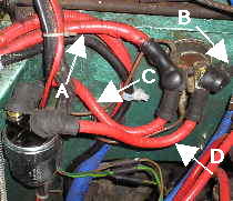
Genuine Lucas SRB316
manual starter switch connected in parallel to the original push button starter switch
A - Main cable from battery
B - Cable from original starter switch to starter motor
C - Cable from new switch to original switch
D -
Cable from new switch to original switch
It's a useful convention to wrap the leads in red insulation tape to mark them as being directly connected to the positive battery terminal ( in the photo - the uppermost red cable in the is part of a dual charge system for a second battery).
2. Drill location holes and securely bolt the switch in place with the button at the bottom (button at the top would mean gravity continues to try to make a connection between the inner contacts!).
3. Measure
distances between the terminals to be connected on each switch, allowing for routing away from any contact that may cause abrasion of the cable to occur. Then make up the leads with battery cable. The eyelet terminals needed have 8mm holes; they should be tightly crimped and soldered onto the cables. But before connecting the eyelets fit appropriate insulating covers for each end. These can be adapted from an old set of ignition leads, as shown in the photo below.
Ignition lead with insulators(top)
Insulators transferred and adapted to use on a switch lead(bottom).
4. Connect the eyelets to the terminals of the new and existing switch as appropriate, ensuring that tension is taken out of the cables by bending them to the required shape.
5.Finally, ensure that the rubber insulation boots are covering the terminals adequately.

************************
(To see previous homepages visit the Homepage Archives link)
**************************
